OUR PRODUCTS
- Flexible IPV6 network design. Can operate in Class B, A, X, N or full mesh using fiber, Ethernet or copper wiring.
- Firewalls - The EST4 proxy firewall uses Advanced Encryption Standard (AES) encryption and secure protocols making it FIPS Pub 197 certified. The FIPS, Federal Information Processing Standards, are the most current and most advanced encryption protocols administered by the National Institute of Standards and Technology (NIST).
- On-board Webserver Remote device-independent access to system status reports.
- Built-in E-mail and E-mail-to-SMS Messaging Instant notification of specific event types sent to appropriate personnel.
- Large Full-color LCD Touch Screen with Tactile Buttons Fast, intuitive access to service and responder functions.
- Five-color LED Indicators System status at a glance, select the color needed during programming, reduces replacement part inventory, maximizes use of available infrastructure.
- Network data, audio data, and telephone data share a single twisted pair or single fiber strand Up to 75 percent less cabling, substantial cost savings in material and labor.
- Backwards Compatibility with EST3 Wiring, devices, and most local rail modules are backward compatible, providing easy migration paths, economical transition to new technology.
- Existing Systems Supporting only Network Data can also Support Voice Audio Upgrades add value and extend capabilities in retrofit situations.
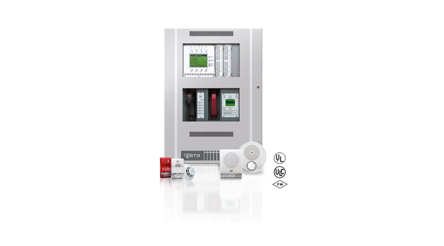
EST3: Life Safety Control Platform
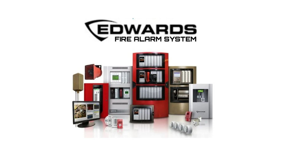
Featuring a new network architecture, EST4 makes fire alarm, mass notification, and building integration easy to implement, quick to service, and secure in the face of today's cyber threats. The result is an emergency communications system equally suited to new and retrofit projects; a platform that keeps property safe and steers people clear of danger.
- Listed for Mass Notification/Emergency Communication, Fire, Security, Access Control, and Emergency Voice Alarm
- 168-character LCD
- Exceptional alarm response times
- Network supports copper, multi-mode fiber, single-mode fiber, or a combination of all three
- Total network wiring over 160,000 feet
- Eight channels of multiplexed digital audio on a single pair of wires or fiber filiment
- Zoned, distributed and banked audio amplifier options
- Local, Proprietary, and Central Station system operations
- In retrofit applications, existing wiring may be used if code compliant
- Supports Edwards Signature Series detectors and modules
- Designed in accordance with ISO-9000 quality standards
- UL864 Ninth Edition Listed
- UL2572 Listed for Mass Notification
- Optional earthquake hardening: OSHPD seismic pre-approval for component Importance Factor 1.5
EST3X: Versatile Life Safety Solution
EST3X represents the latest generation of life safety control panels for mid sized applications. With large multimessage displays and innovative controls, intuitive interfaces, and bold colored cabinets — these systems capture the imagination, and catch the eye. But behind the LCD display is where they really shine. New microprocessors and chipsets take full advantage of the latest advances in computing technology, leading to smarter, faster, higher-capacity processing and more efficient designs.
High performance processing also leads to powerful networking features and versatile digital audio functionality. The wide range of EST3X configurations include standalone operation, networking with up to eight nodes, or integration with an EST3 network comprising as many as 64 nodes — complete with mass notification capabilities and display of security events.
- Up to six intelligent analog loops hosting as many as 1,500
- Signature Series devices per panel
- Optional integrated eight-channel digital audio
- 10amp power supply with universal 94 to 264 Vac
- input voltage
- Patented Voltage Boost™ technology delivers consistent voltage — even at low battery power
- Four built-in 3-amp notification/auxiliary circuits
- Large 24-line by 40-character backlit LCD
- Simplified operation with the SpeedTouch™ rotary control
- 65amp hour battery charger
- 64-node network nodes using copper and/or fiber
- Supports up to 30 R-Series remote annunciators
- Part of an end-to-end audio solution suitable for low frequency
- signaling in sleeping areas
- Space for up to three additional option cards such as extra
- SLC loops, amplifiers, or dialer/modem
- Optional Ethernet Interfaces for central station communication, email, and diagnostics
- 1,100 event history log
- Optional earthquake hardening: OSHPD seismic pre-approval for component Importance Factor 1.5
- UL2572 Listed for Mass Notification, UL864 UUKL Listed for
- Smoke Control, UL864 Listed for releasing applications using SIGA-REL
Featuring a new network architecture, EST4 makes fire alarm, mass notification, and building integration easy to implement, quick to service, and secure in the face of today's cyber threats. The result is an emergency communications system equally suited to new and retrofit projects; a platform that keeps property safe and steers people clear of danger.
- Auto-programming reduces installation time
- Supports Signature Series intelligent modules and detectors
- Combines the Signature intelligent releasing module with
- Signature multisensor detectors for reliable fire suppression
- Electronic addressing with automatic device mapping
- Optional Ethernet port (SA-ETH) for central station monitoring
- service, programming, diagnostics and a variety of system reports.
- Two programmable switches with LEDs and custom labeling
- Supports Genesis horn silence over two wires, and UL
- 1971-compliant strobe synchronization
- Optional multi-protocol Field Server Bridge for interface
- to 3rd party Building Management Systems.
- Ground fault detection by module
- Supports up to eight serial annunciators, (LCD, LED-only, and graphic interface)
- Can use existing wiring for most retrofit applications
- Upload/download remotely or locally
- Optional USB module for local printing or programming using
- the configuration utility on a technician’s laptop.
- Two-level maintenance alert reporting
- Pre-alarm and alarm verification by point
- Adjustable detector sensitivity
- 4 x 20 character backlit LCD display
- Optional earthquake hardening: seismic Importance Factor 1.5
- Standalone operation
- Alarm ON command manually activates alarm condition
- Form C contacts for alarm and trouble, Form A for supervisory
| iO64 | iO1000 | ||
| Device loops | 1 loop Class B or Class A (Styles 4, 6, 7) supporting up to 64 device addresses (any combination of detectors and modules) Maximum T-taps: 63 (each device can be on its own branch) |
1 loop, expandable to 4, Class A or B (Styles 4, 6, 7),
each loop supporting up to 250 device addresses (125
detectors and 125 modules max.). Addresses 1 to 125 are
for detectors and addresses 126 to 250 are for modules Maximum T-taps/loop: 124 |
|
| Notification appliance circuits | 2 Class B (Style Y), Class A (Style Z) optional 3.75 A FWR total at 120/230 VAC 60 Hz 3.0 A FWR total at 230 VAC 50 Hz 2.5 A FWR each max. per circuit |
4 Class B (Style Y) or 2 Class A (Style Z) 6.0 A FWR total at 120/230 VAC 60 Hz 5.0 A FWR total at 230 VAC 50 Hz 2.5 A FWR each max. per circuit |
|
| Primary power | 120 VAC, 60 Hz, 1.3 A max. 230 VAC, 50-60 Hz, 0.62 A max |
120 VAC, 60 Hz, 2.0 A max. 230 VAC, 50-60 Hz, 0.97 A max |
|
| Base panel current standby | 155 mA | 172 mA | |
| Base panel current alarm | 204 mA | 267 mA | |
| Input zones | 16 max. | 32 max. | |
| Remote annunciator | 8 drops max., RS-485 Class B, Class A is optional Data line length: 4,000 ft. (1,219 m |
8 drops max., RS-485 Class A or B Data line length: 4,000 ft. (1,219 m) |
|
| Operating voltage | 24 VDC pane | ||
| Auxiliary power output circuit |
Aux power 1: 500 mA, 24 VDC (1 A possible if you reduce total available NAC power by 500 mA) Aux power 2: 500 mA, 24 VDC Output: 28.3 to 21.9 VDC, special application Note: For a list of compatible devices, see the iO64 and iO1000 Series Compatibility List (P/N 3102353-EN) |
||
| Loop circuit | Maximum loop resistance: 66 Ω Maximum loop capacitance: 0.5 µF Communication line voltage: Maximum 20.6 V peak-to-peak Operating current (fully loaded loop) Stand by: 55 mA/45 mA Alarm: 125 mA/115 mA (not including two-wire smoke modules) Circuit current: 0.5 A max. Style 4, 6, and 7 wiring Max. resistance between isolators: Limited only by overall wire run lengths 64 isolators maximum per loop (total both isolator bases and modules) |
||
| Batteries | Type :Sealed lead acid Voltage: 24 VDC Charging current: 2.47 A max. Amp hour capacity: 26 Ah Standby operation: 24 hour or 60 hour Placement: Up to two 10 Ah batteries will fit in the iO64 control panel cabinet and two 18 Ah batteries will fit in the iO1000 control panel cabinet. If larger batteries are required, use an EDWARDS battery cabinet. |
||
| SA-DACT dialer | Phone line type: One or two loop-start lines on a public, switched network Phone line connector: RJ-31/38X (C31/38X) Communication formats: Contact ID (SIA DC-05) Operating current Standby/Alarm: 41 mA Max.: 100 mA FCC registration number: GESAL01BSADACT Industry Canada Registration number: 3944A-SADACT Ringer equivalence number: 0.1B |
||
| Ground fault impedance | 0 to 5 kΩ | ||
| Alarm contact | Form C N.O. 24 VDC at 1 A (resistive load) | ||
| Trouble contact | Form C 24 VDC at 1 A (resistive load) | ||
| Supervisory contact | Form A N.O. 24 VDC at 1 A (resistive load) | ||
| Environmental | Temperature: 0 to 49°C (32 to 120°F) Relative humidity: 0 to 93% noncondensing | ||
| Terminal rating | All terminals rated for 12 to 18 AWG (0.75 to 2.5 mm²) | ||


